
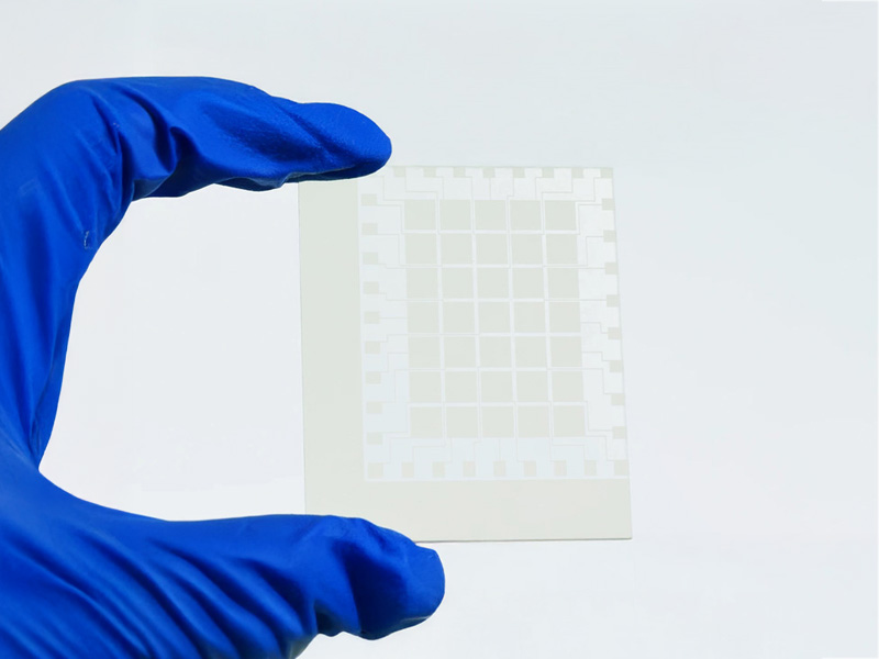
Understanding Sheet Resistance in ITO Glass
Sheet resistance, expressed in ohms per square (Ω/□), is used to describe the electrical resistance of thin conductive films independent of their lateral dimensions. For ITO (Indium Tin Oxide) coated glass, sheet resistance is a key parameter for evaluating the electrical conductivity of the coating while maintaining optical transmission.
In applications such as touch panels, display components, and photovoltaic devices, sheet resistance measurement is commonly used as part of routine quality control. The measured value is affected by factors including ITO film thickness, deposition conditions, and post-treatment processes such as annealing. As a result, sheet resistance provides a practical reference for assessing coating consistency and electrical performance in ITO glass production.
There are several methods for measuring the resistance of ito glass:
1.The Four-Point Probe Method
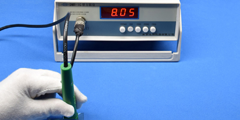
The four-point probe method is the most widely adopted technique for measuring ITO glass sheet resistance. This method employs four collinear probes arranged in a straight line that make contact with the ITO surface. The outer two probes inject a known current through the sample, while the inner two probes measure the resulting voltage drop. This configuration effectively eliminates contact resistance and lead wire resistance, which would otherwise introduce significant measurement errors.
The sheet resistance is calculated using the formula:
Rs = (π/ln2) × (V/I) ≈ 4.53 × (V/I),
where V represents the measured voltage and I represents the applied current. This relationship assumes the sample dimensions are significantly larger than the probe spacing, which is valid for most commercial ITO glass substrates.
Advantages
- High accuracy
- Non-destructive
- Repeatable and standardized (ASTM, SEMI)
Note:
The ITO surface should be clean and free of fingerprints, dust, or chemical residues to ensure stable probe contact. Measurements are typically taken at multiple locations across the substrate to evaluate sheet resistance uniformity and identify potential coating variations.
Probe pressure should be controlled to achieve consistent electrical contact without damaging the ITO layer.
2.Two-Point Probe Method
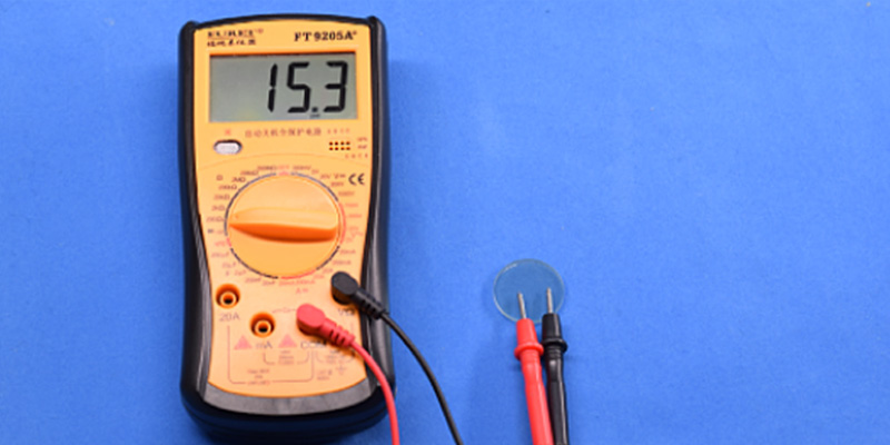
The two-point probe method is a simple and fast approach for evaluating the electrical continuity of an ITO surface. It is typically performed using a standard digital multimeter, with two probes placed directly on the conductive coating to measure resistance between the contact points. Due to its ease of use and minimal equipment requirements, this method is often applied for quick checks during incoming inspection or process monitoring.
However, the measured resistance is strongly influenced by non-ideal factors, including contact resistance at the probe–ITO interface, probe resistance, and lead wire resistance. As a result, the obtained values do not represent the true sheet resistance of the ITO layer. Measurement results can vary significantly with probe spacing, applied contact pressure, and surface conditions such as contamination or oxidation.
Applications
- Rapid pass–fail screening
- Comparative evaluation between samples with identical geometry
- Preliminary checks under consistent measurement conditions
Limitations
- Low accuracy
- Strong dependence on operator technique and test conditions
- Not suitable for absolute or standardized measurements
note:
The two-point probe method should not be used to report sheet resistance values in product specifications, datasheets, or formal quality records.
3.Van der Pauw Method
The Van der Pauw method is a high-precision technique used to determine the sheet resistance of conductive thin films, including ITO, on samples with arbitrary shapes. This method employs four electrical contacts placed along the perimeter of the sample rather than in a linear arrangement. Current is sequentially applied between two contacts while the resulting voltage is measured across the remaining two, with multiple configurations required to complete the calculation.
Accurate implementation of the Van der Pauw method requires well-defined sample geometry and the formation of stable ohmic contacts. These contacts are typically created through metallization, soldering, or the use of conductive adhesives, which often involve additional processing steps and may permanently alter the sample.
Applications
- R&D characterization of ITO thin films
- Electrical analysis of samples with complex or irregular shapes
- Fundamental material property studies
Limitations
- Requires sample preparation and ohmic contact formation
- Potentially destructive to finished substrates
- Not suitable for high-throughput or inline production testing
due to its complexity and sample preparation requirements, the Van der Pauw method is rarely sed in routine manufacturing environments.
Typical Sheet Resistance Ranges for ITO Coatings
10–20 Ω/□ This range represents low-resistance ITO coatings designed for applications where high electrical conductivity is critical. Such coatings are commonly used for electromagnetic interference (EMI) shielding, transparent heaters, and certain industrial or aerospace components.
50–200 Ω/□ This is the most widely used sheet resistance range for commercial ITO glass, especially in touch panels, LCD and OLED displays, and general optoelectronic interfaces.
300 Ω/□ and above High sheet resistance ITO coatings are primarily selected for applications where maximum optical transparency is prioritized over electrical conductivity.
In Summary
The four-point probe method provides the most reliable approach for ITO glass resistance measurement in production environments. Establishing proper measurement protocols and incorporating these The four-point probe method provides the most reliable and industry-accepted approach for measuring ITO glass sheet resistance in production environments. In our manufacturing process, this method is routinely used as the standard measurement technique to ensure accurate, repeatable, and comparable results across batches.